Showing posts with label TIP120. Show all posts

Sunday, March 29, 2015

Wateringduino (again)

Though I have posts about wateringduino, I haven't show it on the field, so, here it is:
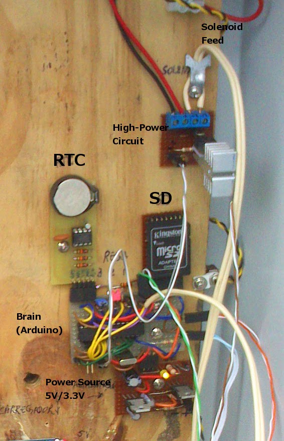
On top-right I have the TIP120 power circuit to drive the solenoid open/closed when strawberries dry, you can't drive the solenoid directly, it works on 12V, arduino uses 5V and the current it drains (about 800 mA) would blow up the ship even if it used 5V. On the left there's the RTC (Real-Time clock) which supplies the date/time for the logging purposes, with this I know exactly at what time it waters the strawberries and allows a more advanced logger (spreadsheet graphics allowed), as we saw in a previous post. The SD label is an SD shield with a 32 Mb (yes, it's more then enough, and I have to recycle things) microSD card in which the .csv data files are recorded. The "brain" is the arduino circuit, homemade as it gets cheaper than using a bought board, it has (as previous posts refer) 3 circuits only one is working now, just because the other 2 solenoids haven't arrived yet, it will water the trees and blueberries/raspberries/blackberries very soon. The item marked as power-source is as it is, a power-source, which receives 12V DC and generates 2 outputs, one of 5V for arduino and stuff and one of 3.3V for the SD card. IMPORTANT: never try to drive SD cards with 5V, you'll blow them up!
On the left, is a picture of the homemade probe which measures the moist in the soil, the pic was taken a couple weeks ago and the berries are quite bigger now. I must say that the dry-up problem they had last year no longer happens!
I'll get back to this as soon as I get the ordered solenoids, and I'll post the code also, which has changed since the last time, namely the .csv file format as I realized that the old format wasn't graphic friendly, it needed a lot of hammering to get it compliant with the needs.

Cheers!

Friday, January 2, 2015

The TIP120 Arduino shield

  This article is about a homemade Arduino shield, using a TIP120. The TIP120 is a darlington transistor that works as an electronic switch, it can handle large power, such as 60 Volt, 5 Amp (for high power you should use an aluminum cooler). This approach has some advantages over a relay circuit, and some disadvantages too, as you all can imagine, one of the disadvantages is the use of 110/220V circuitry as the TIP only works with 60V, on the other hand you can use PWM on it, it is faster than a mechanic switch as the relay and I imagine it consumes lower power on switching than the relay.
I used the circuit on the right (which I found somewhere over the internet) to build a schematic as you can see on the image at the
right to build afterwards an Arduino shield.


At the top of the image we see the TIP and the Arduino connection, the Arduino signal (that can be a regular digital output with an on/off behavior, or a PWM digital output to provide dimming on a lamp/LED or motor) and the GND provided by the Arduino board. On the lower end of the schematic we have 2 board connectors, one for connecting the load with the polarity showed (the polarity is only important on devices which have one, in case of a DC motor the TIP is protected by a diode 1N4007 or similar) and the other to connect the power. The 1 k Ohm resistor should be replaced by a 4k7 because of ground fluctuations.
The final result can be seen in the pictures.


NOTE: Has been registered a situation where the input control pin had a fluctuating voltage and the load and power were connected leading the TIP to a ON false situation, a workaround could be increase the resistor value or ground the control pin. Not tested yet.