Sunday, March 29, 2015

Wateringduino (again)

Though I have posts about wateringduino, I haven't show it on the field, so, here it is:
On top-right I have the TIP120 power circuit to drive the solenoid open/closed when strawberries dry, you can't drive the solenoid directly, it works on 12V, arduino uses 5V and the current it drains (about 800 mA) would blow up the ship even if it used 5V. On the left there's the RTC (Real-Time clock) which supplies the date/time for the logging purposes, with this I know exactly at what time it waters the strawberries and allows a more advanced logger (spreadsheet graphics allowed), as we saw in a previous post. The SD label is an SD shield with a 32 Mb (yes, it's more then enough, and I have to recycle things) microSD card in which the .csv data files are recorded. The "brain" is the arduino circuit, homemade as it gets cheaper than using a bought board, it has (as previous posts refer) 3 circuits only one is working now, just because the other 2 solenoids haven't arrived yet, it will water the trees and blueberries/raspberries/blackberries very soon. The item marked as power-source is as it is, a power-source, which receives 12V DC and generates 2 outputs, one of 5V for arduino and stuff and one of 3.3V for the SD card. IMPORTANT: never try to drive SD cards with 5V, you'll blow them up!
On the left, is a picture of the homemade probe which measures the moist in the soil, the pic was taken a couple weeks ago and the berries are quite bigger now. I must say that the dry-up problem they had last year no longer happens!
I'll get back to this as soon as I get the ordered solenoids, and I'll post the code also, which has changed since the last time, namely the .csv file format as I realized that the old format wasn't graphic friendly, it needed a lot of hammering to get it compliant with the needs.

Cheers!

Wednesday, March 18, 2015

Arduino ISP shield

Hi there! I finally managed to get the ISP shield on tracks, here you have some pictures, I just need some fresh ATmega328 to use it! :)

Initial circuit and pieces
Piezo soldered
Piezo and Leds in place
On top of the main board, quite nice ah?..
Downside, a little messy, but better hidden than at sight!!!

Tuesday, March 17, 2015

Nano drivers

Well... I bought a Chine Nano, and it turned out to be a replica with a ch340g cheap chip, I followed these guidelines after some hours trying to install updated arduino drivers with no success, hope this will help those who read this...

Thursday, March 12, 2015

Dallas DS1820

Well... I needed to use a long cable to acquire a couple of temperatures and I was having problems with the readings. The specs say that long cables can be used (something like 300 meters) and several devices, BUT reading some more I found out that these are supposed to have repeaters along the way. Nevertheless I found this information which I quote:
For short cable runs, unscreened two- or three-core cable, or single-core (parasite mode) or twin-core (normal mode) screened audio cable should be suitable. For longer cable runs, low capacitance cable such as rf aerial downlead (parasite mode) has been successfully used over a distance of 10 m. CAT 5 network cable has also been used with success over a distance of 30m, with data & ground using one twisted pair and power & ground using a second twisted pair. 
 I managed to put the DS1820 working with some cheating, and not using these recommendations, instead of the shielded cable and stuff, I used a pull-up resistor of 2000 Ohms, instead of the 4k7 which is usually recommended/used. It works, maybe the resolution is not the best, but in fact I'm not using all the cable I tested so, it's a cheaper way of doing what I wanted. The large distance was achieved in parasite mode, in regular mode the results would be even better.

Back to wateringduino!!

Well... The Summer is coming, we're almost at Spring time and I bought a solenoid and finally got the wateringduino on the field. This year I'll have fantastic strawberries I can assure!
I made some changes to the project, and I'm still adapting it to the needs I have, so, let's see:

- Circuit 1; Watering the strawberries based on data collected by the probe. I found out that it works fine but there's an adjustment needed to guarantee that the moist level doesn't change so drastically during daytime with the temperature change.
- Circuit 2; I intend to improve and change this circuit to water the raspberries and blueberries during daytime within the most warm hours in two small periods of time (4 minutes only), once before 12:00 and another afterwards, to keep the roots slightly wet but not too wet. A probe will not be used, I'll use the RTC instead to do the job.
- Circuit 3; Is to be changed, not using probes, using the RTC instead, as in circuit 2 but in this case watering the trees daily for 20 minutes, probably a couple hours before sunrise.

I leave some graphs I got from the SD logger that wateringduino has implemented.
The first one (on the left) is a temperature graph of an underground probe, about 0.5 meter beneath soil surface.

The second one (on the right side) is the moist values the system got, and as you can see it needs some adjustment because the moist values don't change that much during daytime, so, what's happening is that conductivity changes with the heat, and as the strawberry "vase" is hanged at about 1 meter height, it get's warmer with the sun rays during daytime, hence, the voltage gets higher within warmer conditions. The corrective formula (there are also corrective tables, but the application of an equation is easier to do) is this one:
I haven't decided yet if I'm going to use it, after all it's extra hard-work as a tradeoff of cleaner data, so... Nevertheless it means that the electric conductivity at 25 Celsius is equal to the obtained electric conductivity multiplied by an exponential factor which has the soil temperature within it, aimed to balance the data.
The orange spikes concern the moments that the system starts watering.
As you can see the system is working fine and I have now nicely wet strawberries! Cheers!

Friday, January 9, 2015

HC-06 Bluetooth module with arduino.

Hi there! This is a short document/code to remind me what I have done with a HC-06 Bluetooth module and an arduino as it's not easy to collect the information I got here, it took me sometime.
Firstly, the module can be AT controlled and set some of the parameters as long as it's not paired with a device, so, we must first set the parameters and only afterwards play with devices. The password/pin of the device and name are not lost upon power off.
The AT available commands are:
- AT -> OK (shows status) 
- AT+VERSION -> OKlinvorV1.8 (shows firmware version)
- AT+NAMEARDUINO -> OKsetname (sets broadcast name to 'ARDUINO', kept after powerdown)
- AT+PIN1303 -> OKsetPIN (sets PIN to '1303', kept after powerdown)
- AT+BAUD4 -> OK9600 (sets the baudrate @9600,
   1---------1200
   2---------2400
   3---------4800
   4---------9600
   5---------19200
   6---------38400
   7---------57600
   8---------115200 ) 

Now, knowing this, let's PLAY!! ;)

// HC-06 Possible commands, HC-05 are different!
// ATTENTION!!! THESE COMMANDS WORK ONLY IF THE BLUETOOH IS
// NOT PAIRED WITH ANY DEVICE:
// «AT Mode: Before paired, it is at AT mode.
// After paired it’s at transparent communication.»
// (case sensitive commands)
// AT -> OK (shows status)
// AT+VERSION -> OKlinvorV1.8 (shows firmware version)
// AT+NAMEARDUINO -> OKsetname (sets broadcast name to
//   'ARDUINO', kept after powerdown)
// AT+PIN1303 -> OKsetPIN (sets PIN to '1303', kept
//   after powerdown)
// AT+BAUD4 -> OK9600 (sets the baudrate @9600,
//   1---------1200
//   2---------2400
//   3---------4800
//   4---------9600
//   5---------19200
//   6---------38400
//   7---------57600
//   8---------115200 )

#include <SoftwareSerial.h>

SoftwareSerial BTSerial(10, 11); // RX, TX

void setup() 
{
  // Open serial communications and wait for port to open:
  Serial.begin(9600);
  BTSerial.begin(9600);
  Serial.println("Enter your AT command:");
}

void loop() // run over and over
{
  if (BTSerial.available())
    Serial.write(BTSerial.read());
  if (Serial.available())
    BTSerial.write(Serial.read());
}

Friday, January 2, 2015

The TIP120 Arduino shield

  This article is about a homemade Arduino shield, using a TIP120. The TIP120 is a darlington transistor that works as an electronic switch, it can handle large power, such as 60 Volt, 5 Amp (for high power you should use an aluminum cooler). This approach has some advantages over a relay circuit, and some disadvantages too, as you all can imagine, one of the disadvantages is the use of 110/220V circuitry as the TIP only works with 60V, on the other hand you can use PWM on it, it is faster than a mechanic switch as the relay and I imagine it consumes lower power on switching than the relay.
I used the circuit on the right (which I found somewhere over the internet) to build a schematic as you can see on the image at the
right to build afterwards an Arduino shield.


At the top of the image we see the TIP and the Arduino connection, the Arduino signal (that can be a regular digital output with an on/off behavior, or a PWM digital output to provide dimming on a lamp/LED or motor) and the GND provided by the Arduino board. On the lower end of the schematic we have 2 board connectors, one for connecting the load with the polarity showed (the polarity is only important on devices which have one, in case of a DC motor the TIP is protected by a diode 1N4007 or similar) and the other to connect the power. The 1 k Ohm resistor should be replaced by a 4k7 because of ground fluctuations.
The final result can be seen in the pictures.


NOTE: Has been registered a situation where the input control pin had a fluctuating voltage and the load and power were connected leading the TIP to a ON false situation, a workaround could be increase the resistor value or ground the control pin. Not tested yet.


Friday, August 2, 2013

Burning bootloader - Part 2

Well, I had some problems recording the UNO bootloader on the first experiences, and got stuck with 2 chips "bricked", now that I have some spare time, got back to them and found a shield/guide of how auto-recording the chips, and how to recover them, the code is here and the way to connect the pins of the chip which you want to burn, are here:
  • Pin 1 to digital 10 - Blue 
  • Pin 7 to 5V - Red 
  • Pin 8 to Ground - Black 
  • Pin 9 to digital 9 - Gray 
  • Pin 17 to digital 11 - Brown 
  • Pin 18 to digital 12 - Orange 
  • Pin 19 to digital 13 - Yellow 
  • Pin 20 to +5V - Red 
  • Pin 22 to Ground - Black 
The configuration is an arduino board and a breadboard with the chip which needs to be recorded/the "bricked" one. After connecting the pins to the second board (as described) you should upload the code to the arduino, select:
"Tools-> Programmer->Arduino as ISP"
 and "Tools->Board->Arduino Uno" proceed as in the picture:
It worked for me and I "unbricked" the chips, you can see the entire article here.
This procedure will work on ATmega328P-PU and ATmega328P-PN, for the ATmega328-PU you will have to use the following workaround:
Workaround for ATmega328-PU:
 
In your Arduino folder, find the subfolder: ..\hardware\tools\avr\etc
Make a backup copy of the file: avrdude.conf
  1. Open the file avrdude.conf in a text editor
  2. Search for: 0x1e 0x95 0x0F (this is the ATmega328P signature)
  3. Replace it with: 0x1e 0x95 0x14 (this is the ATmega328 signature)
  4. Save the file 
  5. Proceed as described previously 
  6. Restore the avrdude.conf to it's original settings

The standalone project is here, hope someday to have time and € to do one, for myself!

Update on the 12 February 2015: Gave up on standalone project, because it does not use the optiboot code and does not work very well, or not at all. I will build a shield to burn the UNO's using things explained within this article. Also updated the code link to a 2011 routine, instead of the 2009.
Update on the 13 February 2015: Gave up of the updated 2011 routine, didn't work for the ATmega328P-PN, back to the fine 2009.

Monday, July 1, 2013

Soil moist monitor/manager and logger!

The 'what if' problem...
This project started with a LED, a moist probe and an arduino. Then I thought "what if" adding another probe? After that, "what if" adding an SD shield to log the values? 
When done, "what if"... You understand what I mean, I'm sure. 


So this ended up in a complex system as described:


- 3 Moisture probes, (max) which can be grounded (with a jumper or so) this way you can use from 1 to 3 probes as you need them. (as the one you can see in the picture)

- 3 Solenoid outputs, which will set up the watering of each probe plant (solenoid 1 will open if soil moisture probe 1 alerts for a thirsty plant.)
- 1 Digital thermometer, to log temperature.
- 1 LED.
- 1 Press button.
- 1 RTC (pointless to have a logger without date/time).
- 1 SD shield and card to retain system data.
- 1 arduino board or a DIY arduino board.
My self made board design can be viewed in the picture:
 Now, the most important, how does all this works?
You use as many probes as you want, with a maximum of 3, and connect all the devices, the system boots up, and the led will give you information about the moist:
- 2 blinks - too wet... :(
- 1 blink - GREAT! 
- Fading - too dry.

In the last state, the output pin for the solenoid will turn HIGH and open a TIP120 or a relay circuit (not done yet) to open the solenoid and then water the plant.
The time of each reading is 15 minutes, which changes to 2 minutes when a plant is dry and the solenoid opens, to assure a more accurate watering.
There is also a press button for knowing the water needs at any time, once pressed, 1 second or so later the LED gives you the information needed, not written to console nor SD card.
The logger has a format like this:

Initializing SD card... Warming up!! Starting!!!
Date    Time    Temperature    Pb1    Pb2    Pb3    V1    V2    V3    Ws1    Ws2    Ws3
2013-07-01    20:41:59    24.50    81.64    76.27    76.56     4.08     3.81     3.83    0    0    0   

 
It can be worked out in a spreadsheet or any program that deals with this kind of data, (separated by tabs). A file is created EACH month with a name like "201306.csv" which stands for the year and the month. V1, 2 and 3 are the voltage values read by arduino and Ws1, 2 and 3 are the watering status, a boolean value which is 0 or 1 depending of the watering status, 1 when watering.
I hope You enjoy this, (as I wrote, I have many flavors of this, with several combinations) now go monitor your plants, mine have never been so pretty since I started this, and though I don't have the solenoids working, the LED indications are usefull enough to get them awesome!
The code.The prototype configuration on the picture:
Used this SD library and this RTC library.      

Thursday, May 9, 2013

Burning an arduino bootloader (optiboot)

I got a few samples from Maxim (thank you Maxim) but they came "clean" without the optiboot or anything like that, so I had to burn it down. I used the minimal circuit which can be found on the picture on the right, and here is the procedure:
To burn the bootloader, follow these steps:
  1. Download this hardware configuration archive: Breadboard.zip
  2. Download the latest Optiboot library. 
  3. Create a "hardware" sub-folder in your Arduino sketchbook folder (whose location you can find in the Arduino preferences dialog). If you've previously installed support for additional hardware configuration, you may already have a "hardware" folder in your sketchbook.
  4. Move the "breadboard" folder from the zip archive to the "hardware" sub-folder of your Arduino sketchbook. If you don't have a "breadboard" folder there, create one, an put the file in it.
  5. Restart the Arduino software.
  6. You should see "ATmega328 on a breadboard (8 MHz internal clock)" in the Tools > Board menu.
  7. Upload the ArduinoISP sketch onto your Arduino board. (You'll need to select the board and serial port from the Tools menu that correspond to your board.)You'll find this under "examples".
  8. Wire up the Arduino board and micro-controller as shown in the diagram to the right.
  9. Select "ATmega328 on a breadboard (8 MHz internal clock)" from the Tools > Board menu. 
  10. Under  the optiboot directory, execute the command avrdude -P /dev/ttyACM0 -b 19200 -c avrisp -p m328p -u -U flash:w:"optiboot_atmega328.hex" :i -F
  11. After finished, use: avrdude -p atmega328P -c avrisp -P /dev/ttyACM0 -b 19200 -u -U efuse:w:0x05:m -U hfuse:w:0xDA:m -U lfuse:w:0xFF:m -U lock:w:0x0F:m -F
    otherwise the boot will be recorded/burned, but the chip will not accept uploads.


For ATmega328-PU:
If you try to bootload an ATmega328-PU, you’ll get a message something along the lines of:
avrdude: Device signature = 0x1e9514
avrdude: Expected signature for ATMEGA328P is 1E 95 0F
Double check chip, or use -F to override this check.

You could also get a more colourful version:
avrdude: Yikes! Invalid device signature.

The way to work around this is to “trick” the IDE into believing your 328-PU is in fact a 328P-PU. Disclaimer: I have tested this myself and it works – no guarantees however that you won’t have unforeseen consequences.

Workaround:
In your Arduino folder, find the subfolder: ..\hardware\tools\avr\etc
Make a backup copy of the file: avrdude.conf
  1. Open the file avrdude.conf in a text editor
  2. Search for: 0x1e 0x95 0x0F (this is the ATmega328P signature)
  3. Replace it with: 0x1e 0x95 0x14 (this is the ATmega328 signature)
  4. Save the file 
  5. Proceed as described previously (and use lock:w:0x0F:m)
  6. Restore the avrdude.conf to it's original settings
Good Luck!! Good burnings!

Wednesday, May 8, 2013

RTC shield, I²C, Arduino compatible, DIY

Hi! I'm back, again with arduino and a new shield, once more a DIY shield. 
So, let's start! The picture on the right is the circuit used to build the shield (I want to thank my friend Nuno Portela, who grabed this, and converted to eagle schematic, printing and driling the circuit afterwards).
The schematic on the left is the proposed circuit, which was then printed. All the components are easy to find, so the final result is almost inexpensive.
I've attached also a picture of the final result, 2 boards with cr2032 button cells. 
Concerning the code, I couldn't find where I got mine, so I'm posting it here.
Enjoy!

Saturday, April 27, 2013

Arduino DIY SD shield

Well... I got tired of having the arduino connected to the PC to have a logger, so did some search and ended up with this shield, it uses a micro SD card to SD converter, which is soldered to the board as you can see on picture, the components are easy to find, and they are used to low down voltage from the arduino pins (5V) to something near the 3.3V which is the correct voltage of the SD card. The red cross in the picture means you have to interrupt the circuit on those points, otherwise you would be short-circuiting the resistor. The numbers on the right (10,11,GND,3.3V,13,X,12) are the pins in the arduino board, 3.3V and GND I suppose you know what that means, and X is not connected and is used to align the plug, avoiding upside-down connections.
You can see on the left the final look, without the microSD card adapter:
And on the right side, the final look, already with the adapter soldered.

Enjoy!


Spoiler alert: DO NOT try to connect the card directly to arduino pins, without this voltage divider, you will damage the card!

Based on this shematic.

Test file here and another one here.

Monday, February 18, 2013

Virtual candle (candleuíno) with arduino

Hello! I'm back, after a (more) troubled life period, but still here.
This time I developed something more romantic, something I was looking for a long time now.
What you will need:
  • Arduino
  • A led (clear orange or clear yellow)
  • Resistor for the LED (220 Ohm would be fine)
  • An LDR
  • Resistor for the LDR (10kOhm or 1kOhm would be fine, depends the darkness you want to be triggered)
  • Hot glue stick
  • Paper
  • A wooden box
First you connect the led and resistor as you can see in the picture, you may use any digital pin as long as you change the code to output to it BUT it must be a PWM compatible pin. 
Then you do the same with the LDR, as in the picture, using Analog 0.
Now you have to take care of the LED, it must produce a diffuse light, or it wil be worthless.
So, I used a stick of glue, cut it in about 1 cm, made a hole in it to fit the LED, and inserted it as you can see in the picture below.

I made the circuit and then uploaded to an arduino and hardwired it into a box. The resulting effect is the one in the video. Candle Vídeo
The original project can be found on this page, is slightly different from mine, but it's where I took most of the idea: ledhacker 
Now a picture of the final result:


And finally the code.

Monday, December 19, 2011

Hatchduino (egg hatcher)

Well, this project happened because of lazy chicken... That go eat, sometimes to the shopping mall, for a walk, and the eggs lay in the cold, so something had to be done!
So, the purpose of this project is to make possible to reproduce birds (in this case chickens) without the presence of the mother.

I started by building a wooden box, and isolated with silicon, then used the guide to build the power source, drilled some holes to connect the interior to the outside. At this point I had a PSU and a box, needed something to warm the box, an halogen lamp would be perfect, so got a connector and a zinc tube in the hardware store, what happens here is that the lamp warms the tube, and dissipates heat, not burning the box.

Added a computer fan (that can not be seen in the up picture) like the one on the left, that works inside the tube creating an air flow making the temperature equal all over the box. This item is needed to spread the hot-air within the box, otherwise we would have a very hot area near the lamp and a not so hot, (even fresh during winter) area in the more far point from the lamp. The fan is connected to the +12V/gnd and starts when the PSU is ON, does not have an on/off button, no need.

First tests failed, after one hour of heating the outside of the box would be warm, and the inside not in the proper temperature, so isolating was needed, used then some roofmate isolating boards, worked perfectly, less heating time, more time within the correct temperature without heating (37 degrees celsius).

To the electronic bench now!
After some research I found out that the eggs should be heated to 37/37,5 celcius degrees during approximately 21 days, during this period they should be turned twice a day, and more often on the 3 final days, a wet sponge must be inside the box to soften the egg shell, during the final period this sponge should be wetter.

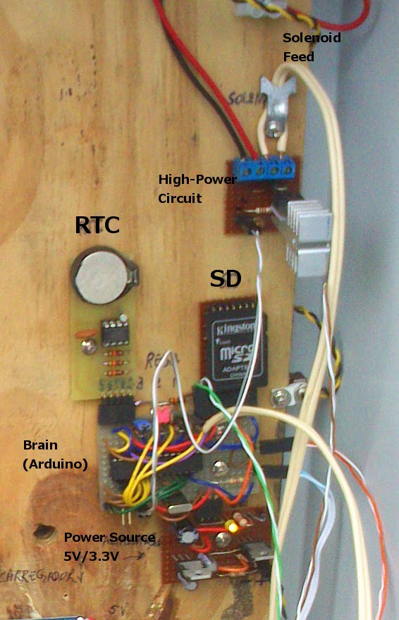
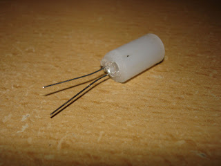
Now for the electronics, I connected an arduino board as you can see on the right, with the LM35DZ inside my box, covering the temperature, and two LED's one to inform the heating on (the yellow, digital output #3) and other to tell me that heating is off (green LED, digital output #4) but the system is alive. The digital #5 is the output to set the relay on/off, using the relay shield built before, where you see "digital port 13", connect the digital #5 as referred previously.

As power source for the relay shield, you should use the +12V/gnd from the PSU, and the same for the arduino, you just have to solder two wires to a proper jack, (like the one in the right) remembering that the +12V go inside and the gnd on the outside. Arduino and relay shield MUST share the gnd, (common ground) otherwise the shield will not work.

On the left there is a picture of the final result, the temperature sensor on the right bottom of the picture, with a green surrounding, far from the lamp, within the egg area. The green arrow shows the air-flow from the fan that stands behind the lamp, distributing the hot-air in the box.

Now with all the hardware set, we need the software, and that, lays here, feel free to change it within the license authorization. Basically you set it on, it starts regarding the temperature indicator, if less than 37 degrees, sets the yellow LED and relay ON for heating purposes, when reaches a comfortable temperature, sets the relay OFF and the green LED ON, and stays controlling the temperature, and the behavior goes on and on, until the birds hatched!

I can tell you the system works fine, and as a final note I leave you the console output.

Materials used:
- Wooden box
- Roofmate isolator
- Arduino
- Old PC fan
- Homemade relay shield (see link)
- Customized PC power source (see link)
- 50W halogen lamp and connector
- Zinc pipe/tube
- Green LED
- Yellow LED
- Power jack
- LM35dz
- Wires, connectors, etc.

Feel free to contact me.

Friday, December 16, 2011

Customized ATX power supply

An old PC power supply! Who does not have one...? For my arduino project I needed a reliable and powerful power source, because of the halogen lamp used to warm the hatch box, so, layed hands on work and converted an old PSU. Let us see how!
As you all may know, these PSU's once connected to the AC power, are ALWAYS in charge, for that I connected an LED, and an other for when the power unit is really on. If your power supply has an on/off button, you can skip the switch connected to the green wire, and just short-circuit it to ground, using the native on/off button to switch on and off.
Nevertheless the left image explains the wires needed to be worked to achieve best results. Did not use the resistor.
The yellow wires are +12V, the blue -12V, the red +5V, the black GND, the yellow +3.3V, white -5V, as you can see on the next picture. You can now drill the box and use some connectors with a fuse to protect the PSU, and voilá!
I used these links, an instructable and a wikihow as an aid to the work. Good luck on your project! Feel free to contact me.

Arduino relay shield (homemade)

Hi! This is my homemade arduino relay shield, I had a spare 12V relay, and nothing to do with it, so this project happened.
The circuit is roughly the version seen in the schematic on the left, with a BC548 (NPN) transistor and a 1N4007 diode, my resistor was of 8220 Ohm.
The ground (GND) has to be the same on the arduino and on the relay shield, or it will not work.
On the picture you can see on the bottom part the + (Vcc), S (signal from arduino, any digital port), and - (GND), on top we see the connectors for NO, (normally opened) C, (common), NC (normally closed).
For the whole article, you can follow the original instructable that I based on, here.Link